Dive Computer Teardown - Versa Pro
October 12, 2018
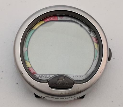
A few days ago I obtained a malfunctioning dive computer along with some other SCUBA gear and decided to do another teardown. This one proved a bit more interesting since none of the chips were blobbed over. (See my previous teardown of a Genesis ReSource dive computer.)
Teardown
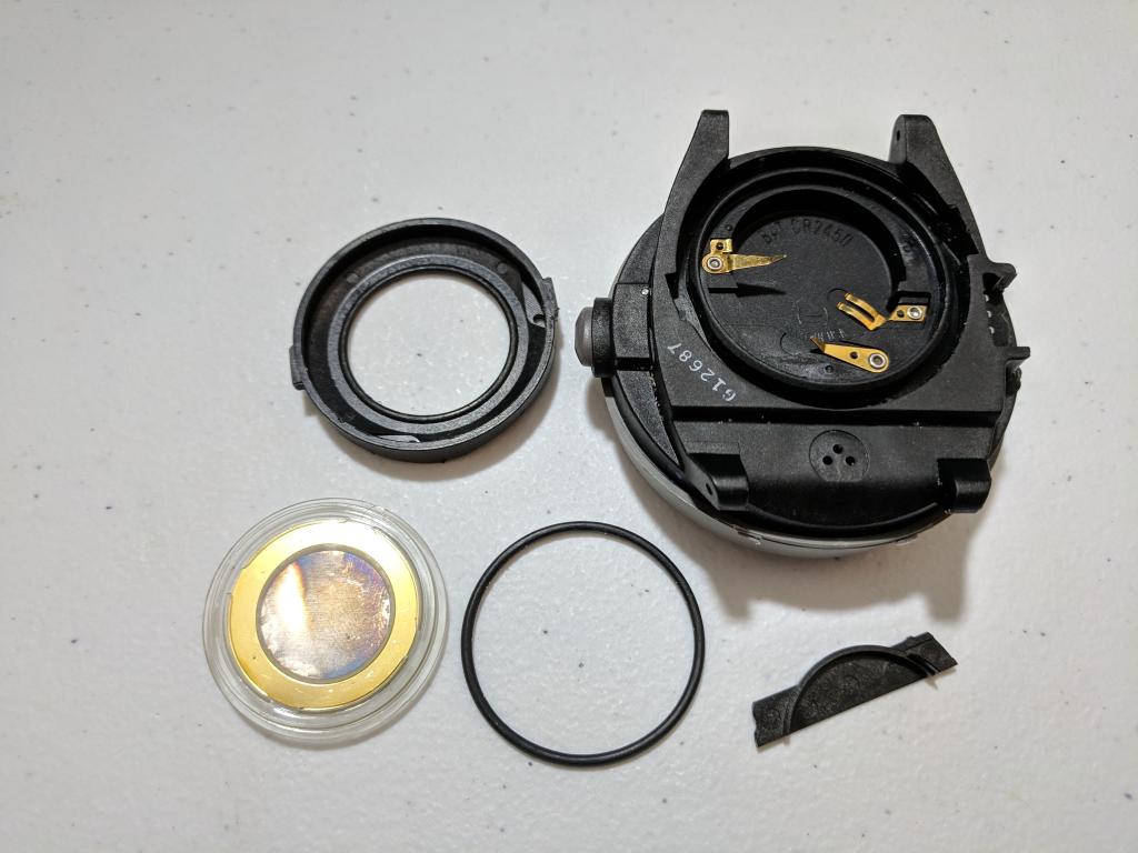
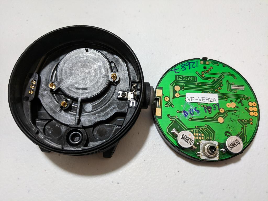
First step, remove the battery. It turns out the hard plastic cover with the copper layers both provides the surface for the o-ring to fit around, and is a piezo buzzer/speaker (more about that later).
The outer metal covering pops off easily with a small flathead screwdriver to pry the clips apart. The grey plastic ring underneath just slides off.
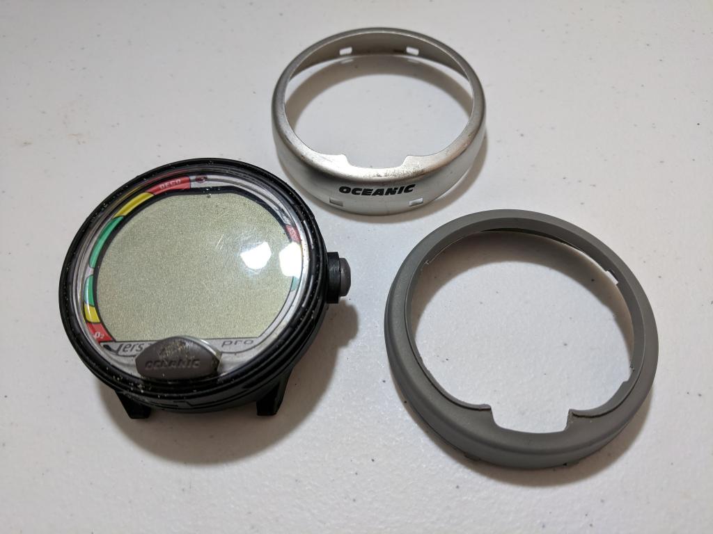
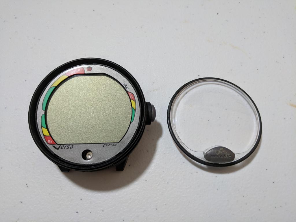
With that, the plastic covering the LCD screen comes right out, along with the o-ring.
And now the screen/circuit board module lifts out. You can see all the little springs which connect the circuit up to the external contacts.
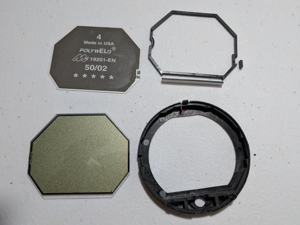
The screen unclips from the circuit board with three little tabs.
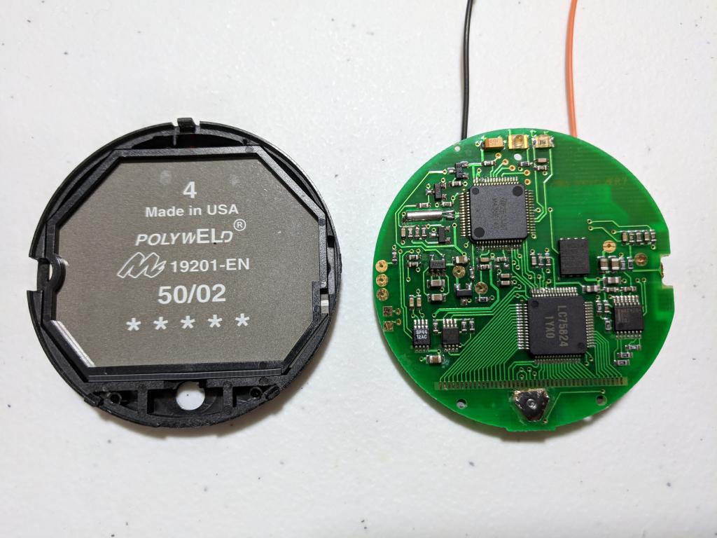
The LCD itself is in the lower left. The polywELD object in the upper left is an electro-luminescent (EL) light which forms the backlight. In the upper right corner you can see two pieces of zebra connector which connect the LCD screen (the long piece) and the EL light (the short piece) to the circuit board.
The Circuit
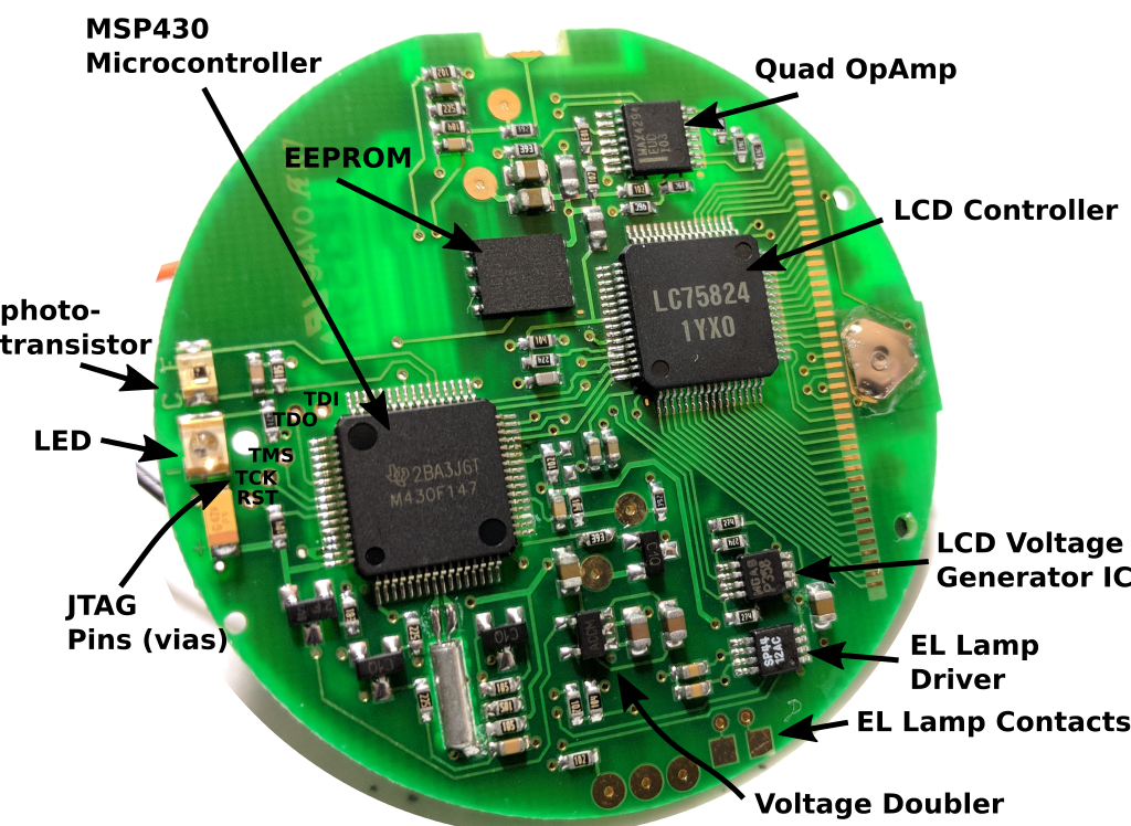
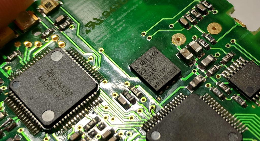
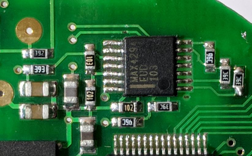
Below you can see labels for all the main components of the circuit. Most of these will be discussed in more detail further down this post.
A closeup to show the text on the EEPROM chip.
The reverse side of the PCB. Note the pads which connect to the springs I pointed out before.

Pressure Sensor
The pressure sensor was giving bad readings according to the error the computer showed. Since the computer is from circa 2003, the manufacturer doesn’t service this model anymore, so no point in being non-destructive.
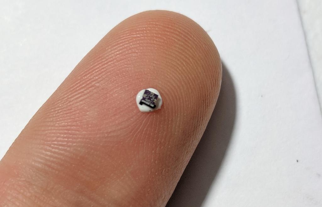
This is tiny module underneath the black protective goop inside the pressure sensor. It measures 1.5mm x 1.5mm x 0.9mm.
And this is the module under a microscope. You can see the locations the bond wires connected before I broke them by pulling it out of the housing.
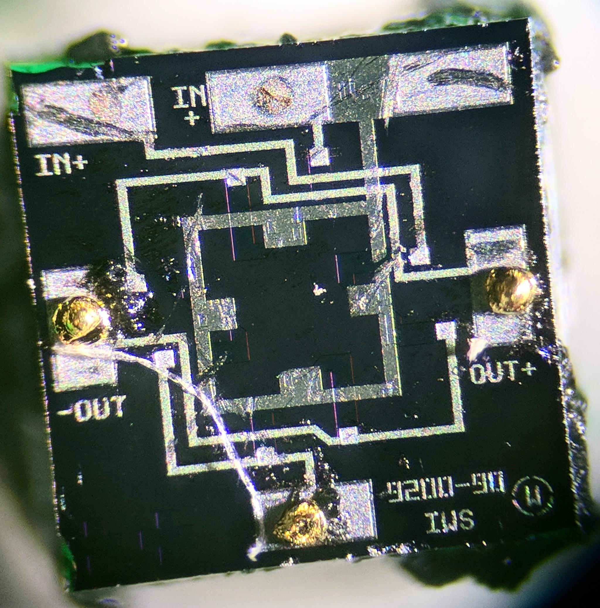
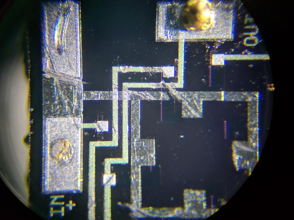
There is definitely some 3-dimensionality to this module. From doing some reading I believe it is a Wheatstone bridge composed of piezo-resistive elements. There is probably a sealed chamber inside for use as a reference pressure. The output signal is a differential analog voltage which goes off to an opamp circuit to prepare a signal which can be measured by the ADC in the microcontroller.
Update: I emailed SMI and asked if they could identify the sensor, and they responded a few hours later that it was the SM5106. In the snippets from the datasheet shown below, you can see that it is indeed a Wheatstone bridge composed of four piezoresistive elements.
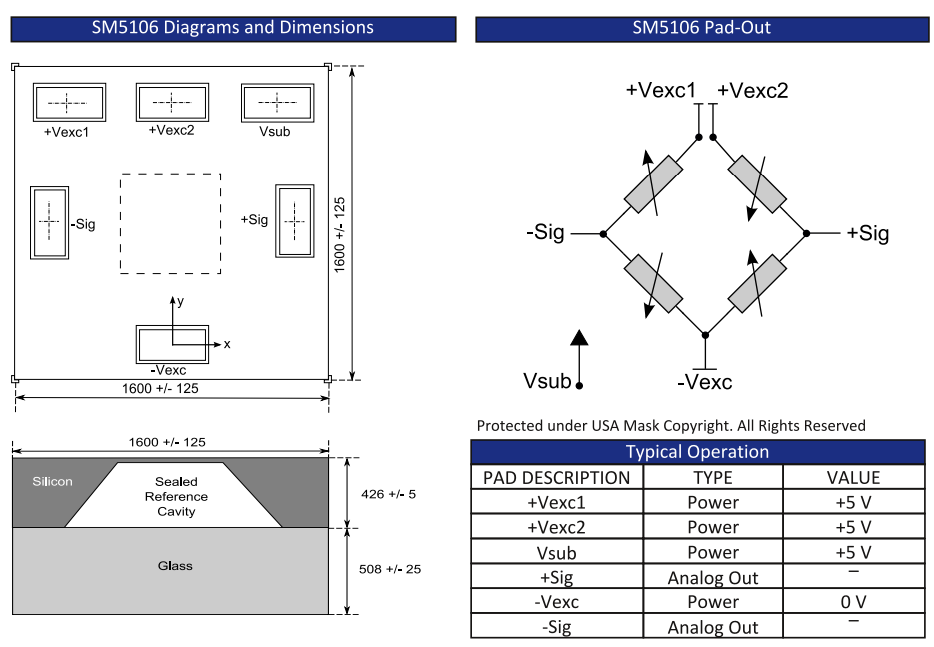
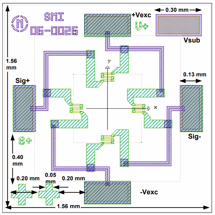
Below is a nearly identical die showing the 4 squiggly bits which form the actual sensing elements.
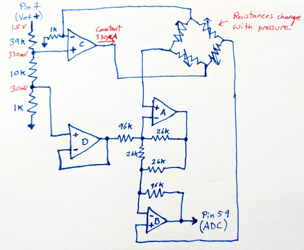
The circuit below conditions the signal coming from the sensor, preparing it to be read by the ADC. It is composed of four opamps and various passives.
As shown in the schematic below, opamp C creates a constant current source pushing 330 uA through the Wheatstone bridge. Opamp D is just a buffer. Opamps A and B form something similar to an instrumentation amplifier, but not quite the standard configuration. The net result is that if the voltage at the non-inverting inputs of opamps A and B is identical, then the output of B will be 30 mV. If the voltage at the non-inverting input of A is higher than at the non-inverting input of B, then the voltage on the output of B will go up. In the reverse situation the voltage will go down, though of course it bottoms out pretty quickly at zero. I suspect the sensor is setup so this situation should never happen.
The output voltage which would be read by the microcontroller can be found using the equation show below. \(V_{A-} \) and \(V_{B-}\) are the voltages at the inverting inputs of opamps A and B. Since they are setup with negative feedback, these will equal the voltages at their non-inverting inputs AKA the voltages from the sense terminals on the Wheatstone bridge.
\( V_{out} = (3\frac{96e3}{26e3}+1)(\Delta V) + 0.03 \) where \( \Delta V = V_{A-} - V_{B-} \)
or approximately
\( V_{out} = (12)(\Delta V) + 0.03 \)
You can see a simulation of the circuit here.
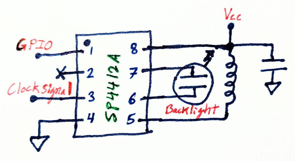
Backlight
The backlight consists of an electro-luminescent (EL) panel shaped to exactly match the LCD. EL panels are a capacitive load (this one measures about 6 nF) which need to be driven by a high voltage AC signal, typically 150 Vpp or more. The IC shown in the circuit diagram below is specifically designed to drive EL lights. It uses the inductor to generate very large voltage spikes at a frequency controlled by a clock signal from the microcontroller.
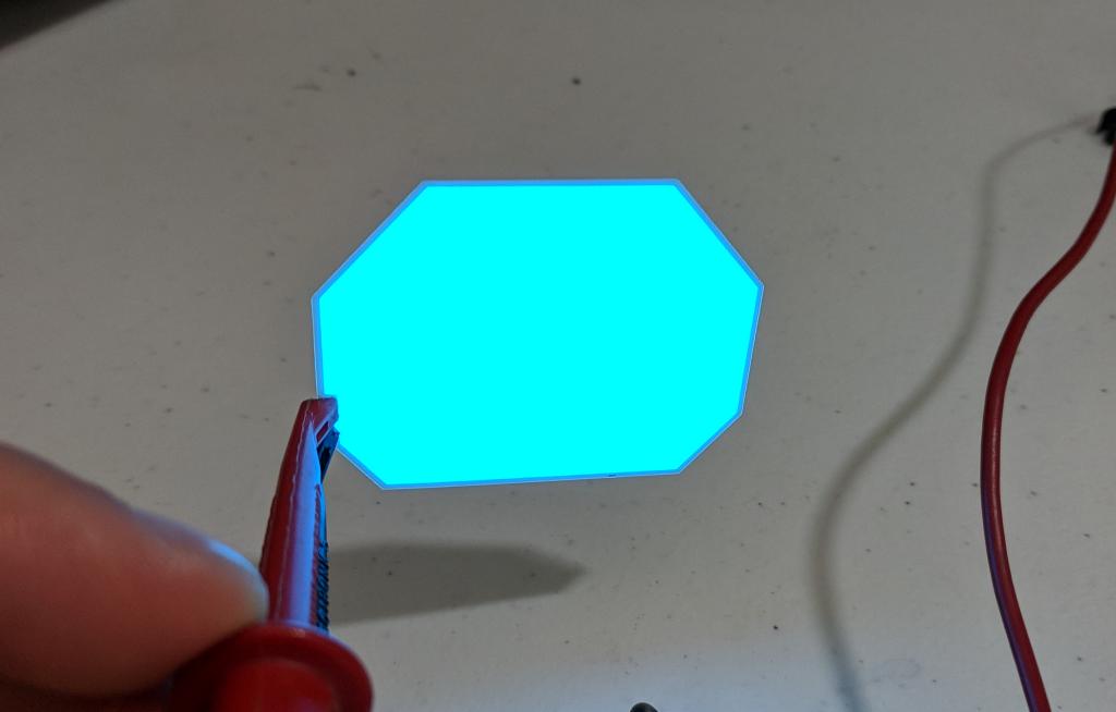
Below you can see the panel glowing. I have it connected to a stand-alone EL driver I have for use with EL wire.
Speaker/Buzzer
I found this circuit especially interesting to understand, since I didn’t realize at first that the back disk behaved as a buzzer. For a while I was thinking that it might be a way to detect the intrusion of water to the battery compartment.
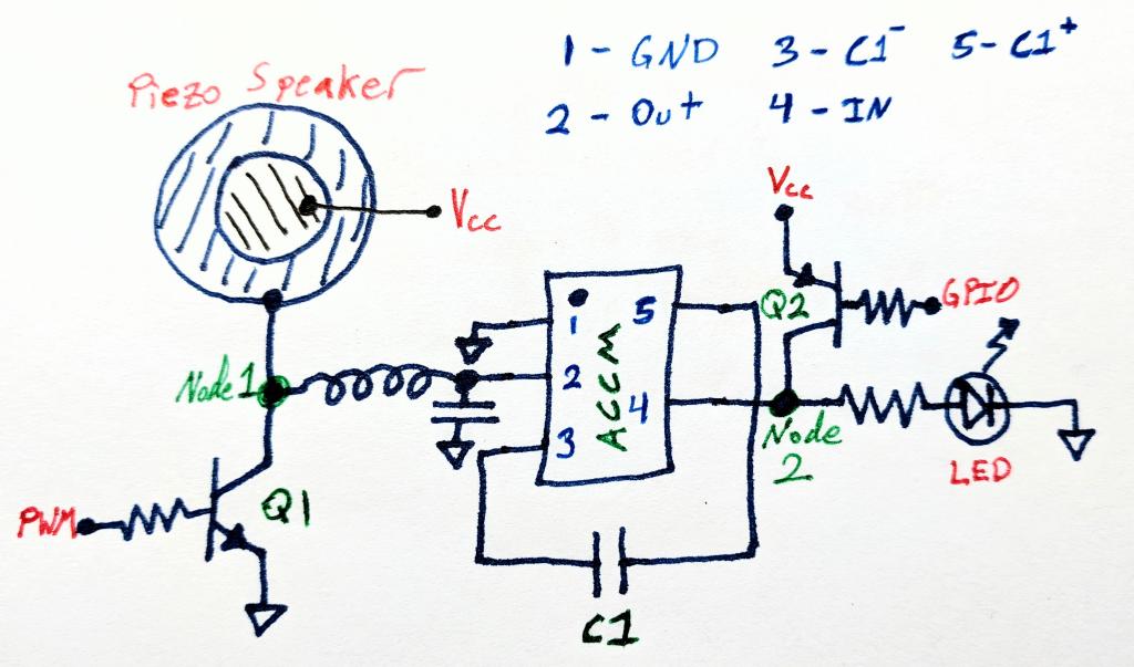
The buzzer consists of two copper plates separated by a small distance. The smaller plate is connected directly to the positive terminal of the battery. Why the positive terminal and not the negative “ground” terminal? I’m pretty sure just because it was more physically convenient, and whether that plate is held at “zero” or at three volts is irrelevant compared to the large voltages on the other plate.
The IC marked ACCM in the circuit below is a simple capacitive charge pump style voltage doubler (See my post about building an inverting charge pump for more info on how these work). When transistor Q2 is turned on (by pulling the GPIO to ground) Node 2 gets connected to Vcc. This turns on the LED and provides the input voltage for the voltage doubler. Pin 2 is then at 6 volts (Vcc * 2).
The fun comes when Q1 is alternately turned on and off by a PWM signal from the microcontroller. When Node 1 is pulled to ground through the transistor, the inductor behaves like a simple wire (in the steady state). But, when the transistor is turned off, current through the inductor attempts to stop instantly and the collapsing magnetic field creates an induced current in the same direction but now this current has no where to go. The result is a large voltage spike at Node 1 which means a large potential difference across the capacitive load (about 12.3 nF) formed by the buzzer. This built up charge then goes back through the inductor resulting in an oscillation which is stopped when the transistor turns back on, pulling Node 1 back to ground.
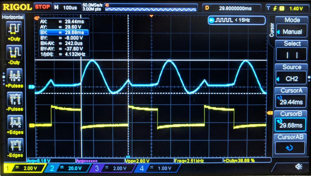
The lower (yellow) trace is the approx 40% +duty cycle PWM signal from the microcontroller. The upper (blue) trace is the voltage at Node 1. The approx 40 volt peak-to-peak oscillation results in the buzzer vibrating at 2.5 kHz (plus harmonics).
LCD Voltage Generation
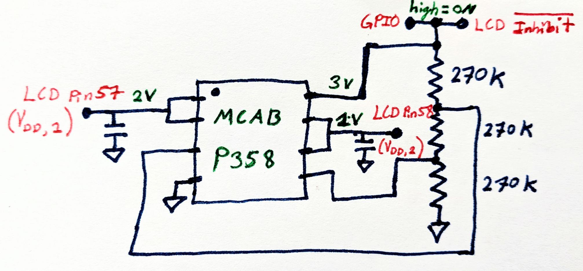
The LCD requires a few different voltages to operate. I couldn’t find a datasheet for the IC marked “MCAB P358” but the purpose is to generate the one third and two thirds Vcc voltages for the LCD driver IC. (See my post reverse engineering an LCD screen for more info on why these voltages are needed.)
Light Sensor
The component beside the LED is (as far as I can tell) a photo-transistor which is used to sense the ambient light levels. The computer manual says it uses this information to only turn on the backlight above water if the computer is in a low light situation. This way battery isn’t wasted lighting up the screen when it isn’t needed. In low light the sense GPIO will remain high, pulled to Vcc by the resistor. In bright light the transistor will turn on, pulling the sense GPIO pin to ground. I suspect that other than for the moment when the microcontroller is checking the light level, both GPIO pins are tri-stated to save power.
![]()
Thanks for reading! Shoot me an email if you caught anything I’m wrong about!