Tube Based Night Light
March 27, 2018
A photoresistor, a couple standard resistors, an LED and a single transistor make a great transistor-as-a-switch demo. The photoresistor’s resistance increases in the dark and it can be used to build a voltage divider which has an increased output voltage inversely proportional to the light level. The output of the voltage divider is connected to the base of a transistor which turns it on or off.

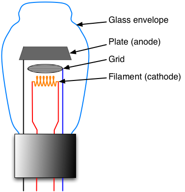
Since I had a box of vacuum tubes hanging around, I was curious to see if I could create the same circuit using a vacuum tube instead of a transistor. The first step was to learn how tubes work in a practical sense. I knew the basic theory but I’d never actually used a tube.
I found the following videos quite helpful:
- US Army Training Film (1943)
- Comparing Transistors and Tubes - AllAmericanFiveRadio
- How a Tube Works - Mr. Carlson’s Lab
After a few iterations I designed a circuit which works quite nicely.

Setting the Quiescent Values
When the photoresistors (LDRs) are exposed to light, the LEDs should be off. For the tube to be “off” the grid needs to be lower than the cathode. Since I didn’t want to deal with generate a negative voltage rail, I set the cathode voltage to be higher than ground using the voltage divider composed of R2+LDR2 and the pot. The grid voltage is set via R1 and LDR1.
The pot should be adjusted until the LEDs are just barely off when the photoresistors are exposed to the desired light level. Around 800 Ohms worked well for the 12AU7, but it depends on the tube you are using. In this state I measured the grid to be about 2.65 V below the cathode.
Operation
When LDR1 is covered its resistance increases and the this forces the grid voltage higher. when just LDR1 covered I measured the grid to be 0.95 volts below the cathode.
When LDR2 is covered the cathode voltage is forced down due to the change in resistance. This makes up for the extra current going across the pot which is trying to force the cathode voltage up. With just LDR2 covered I measured the grid to be 0.77 volts below the cathode.
With both LDR1 and LDR2 covered I measured the grid to be 0.57 volts ABOVE the cathode. This results in significantly more current through the tube and brighter LEDs.
Types of Tubes
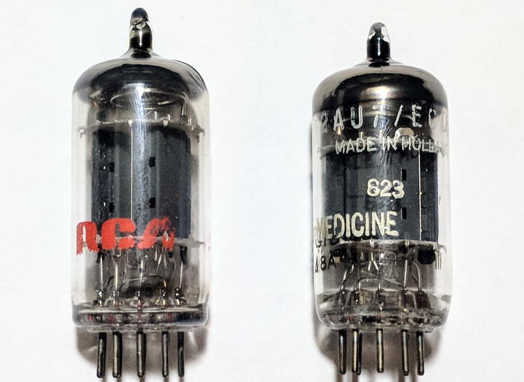
I tried two dual triode tubes, an Amperex 12AU7/ECC82 and an RCA 12AX7.
From the graphs we can get the anode current for a gate voltage of zero volts and an anode voltage of 50 volts.
12AU7: 5.4 mA
12AX7: 1.2 mA
Either current will easily light up an LED, but the larger current should be noticeably brighter. Both tubes have identical pinouts and since each is a dual triode, I can connect the two tridodes in parallel to double the current. This is accomplished by simply connecting anode 1 to anode 2, cathode 1 to cathode 2, and grid 1 to grid 2.
Tube Connections
The picture below shows a BOTTOM VIEW pinout.
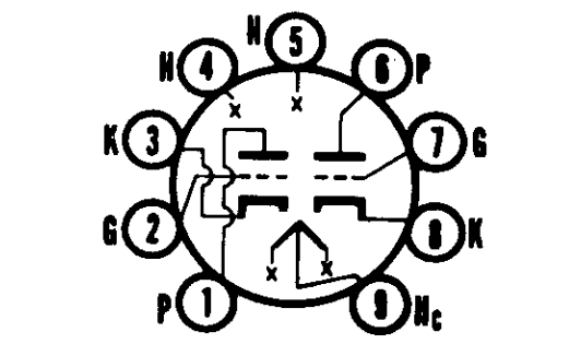
P - Plate/Anode
G - Grid
K - Cathode
Pins 1-4 are associated with one triode and pins 5-8 are the other. Pins 4 and 5 are the two ends of the heater filament and pin 9 is the common center of the filament. Each of the two “sides” of the filament take 150 mA to heat up to the proper temperature. This can be achieved by either not using pin 9 and running 12.6 volts across the entire filament or, as I did in my circuit, connecting pins 4 and 5 together and running 6.3 volts across the combination.
Powering the Circuit
I wanted this to be a nice compact demo unit and so I used a 9 volt battery connected to a boost converter to generate 30 volts. After some testing I found it actually works pretty similarly from 25 up to 40 volts.
For the 6.3 volt rail I simply used the LM317 (variable linear regulator) along with two resistors to set the output close to 6.3 volts. The input comes from the 9 volt battery. (9-6.3)*0.3A = 0.81 watts dissipated in the LM317 which it can easily handle.
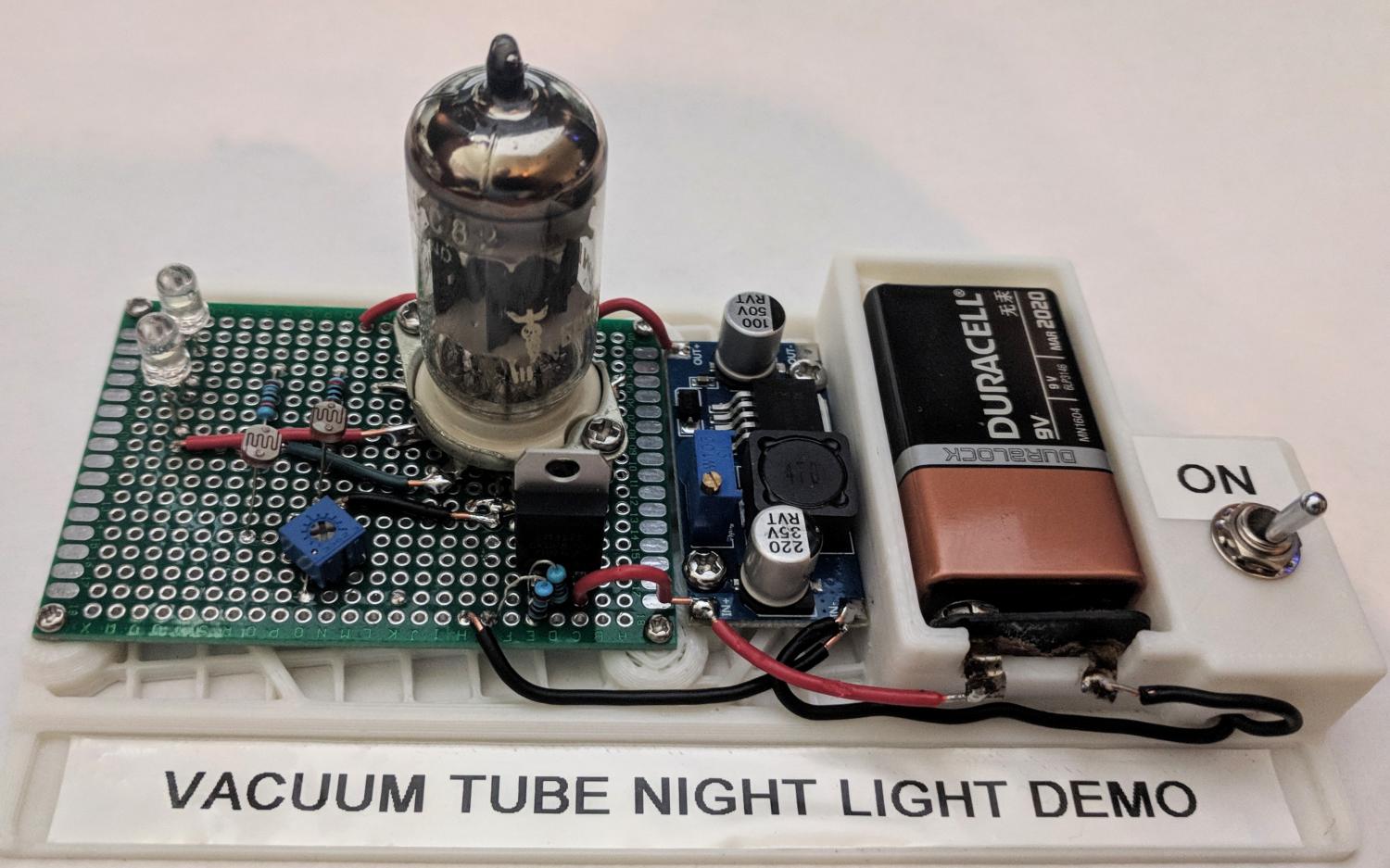
Making it Pretty
I soldered all the components to proto board then designed and 3D printed a base for everything to attach to. I also added a switch to disconnect the battery from the rest of the circuit since even with the LEDs off, the heater filament is still using nearly 2 W on a constant basis which will drain a 9 V battery in just a few hours.
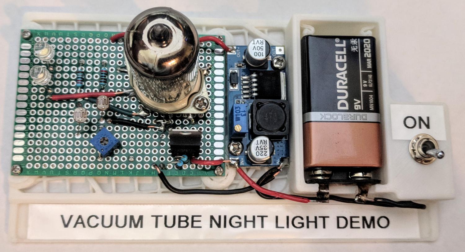
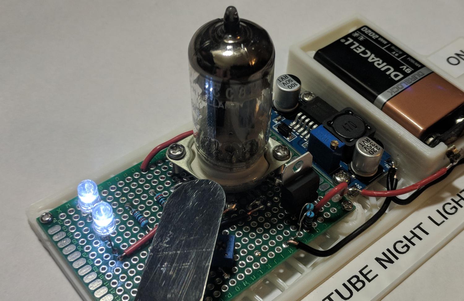
Of course this is an incredibly inefficient circuit, but it makes a fun demo to show how a tube can be used as an electronic switch and to show why transistors are so much better in so many ways.