Teaching an old scope new tricks.
November 19, 2016
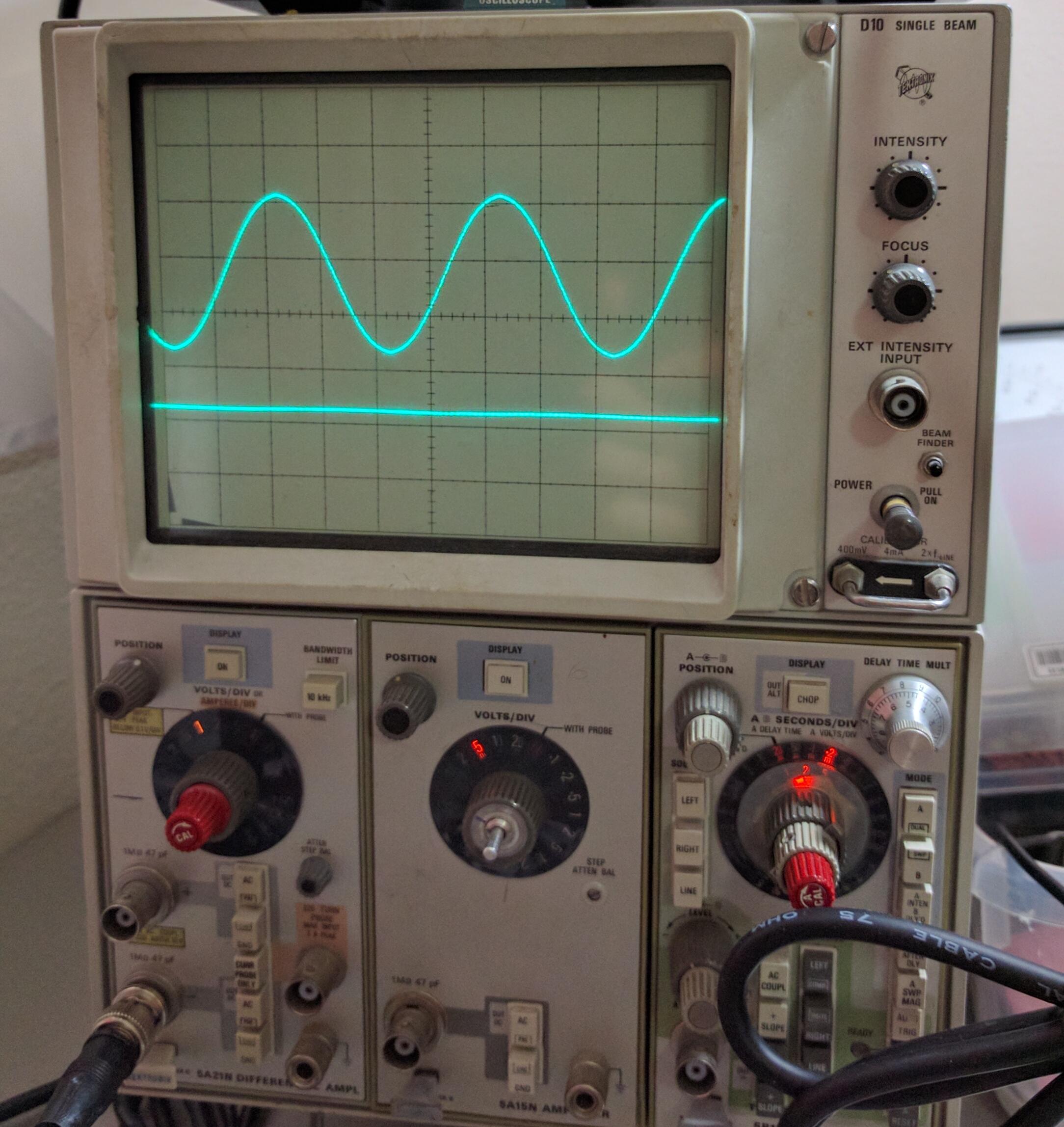
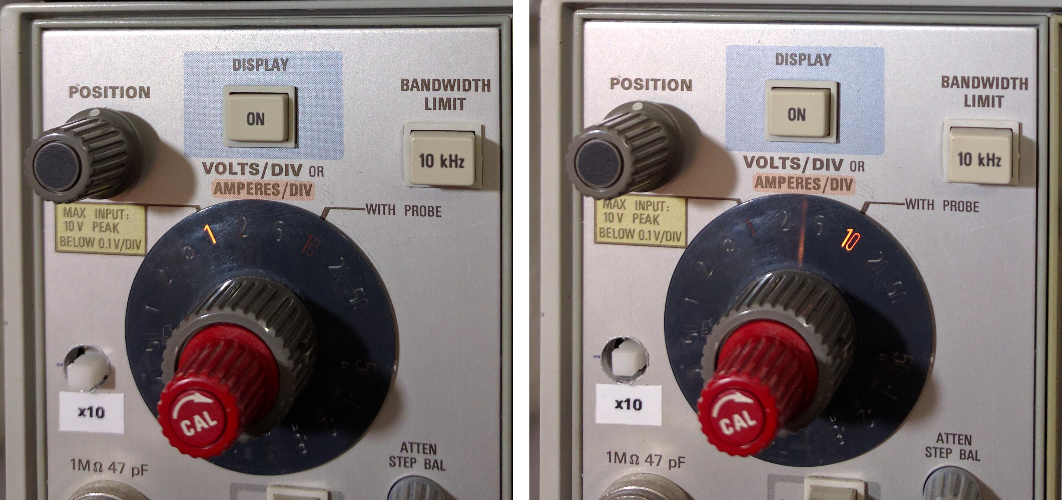
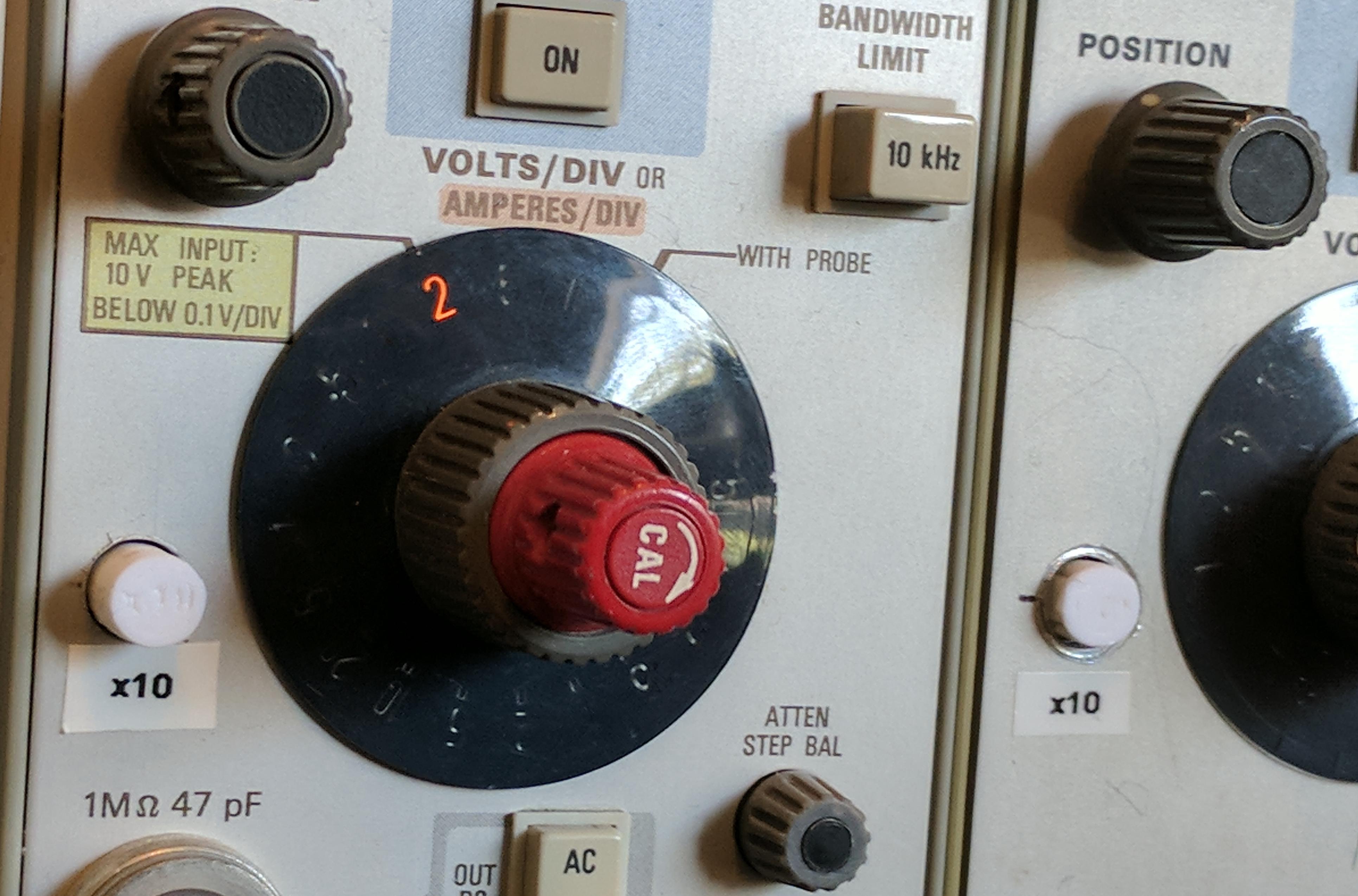
I have an old analog Tektronix oscilloscope I use for my home projects which has served me quite well over the last couple years. One gripe I do have is that when I switch my probe to x10 attenuation mode, the backlight on the voltage dial shows the wrong number. If I was using the proper Tek probes there would be a little pin which would connect to the metal ring around the BNC connector on the scope. This would tell the scope when I switched in to x10 mode and switch the backlight position on the voltage dial. This would be especially useful for when I take pictures of the scope display for future reference and I need the numbers in the picture to be correct, not off by a factor of 10.
As a poor grad student, I’m not going to go spend money on new probes just for this minor feature. Instead I decided to install a switch for each channel which would allow me to manually change the voltage backlight as needed.
Of course the first thing to do is dive into the data sheet and figure out how the lights are connected. Fortunately the data sheets are all available online. Since this scope is modular, there is a data sheet for each of the three modules and a overall data sheet for the scope body. I have two different amplifier modules, but the lights work the same in each. Here is the data sheet for the simpler one, the 5A15N.
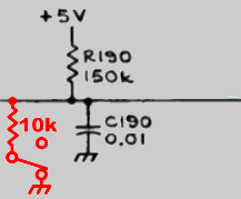
I found a promising looking section of the schematic (shown below, red additions mine) which noted “with probe”. When I looked up DS191 and DS192 I found that they are indeed neon indicator lamps.
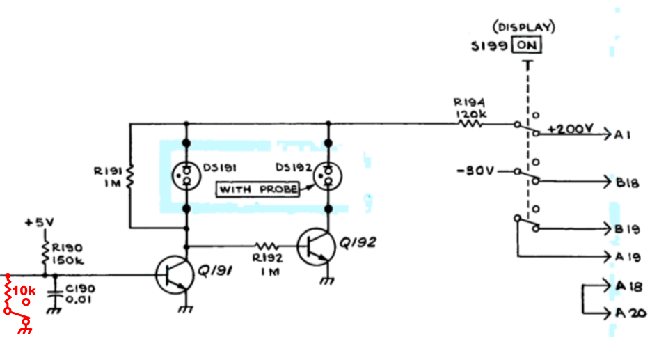

The base of transistor Q191 is normally pulled high by R190. This both connects the x1 light to GND (completing its circuit) and keeps the base of the transistor Q192 low and thus the x10 light off. So I just need to make a switch to pull the base of Q191 low which will result in the base of Q192 being pulled high (by the 1 MOhm resistor) thus completing the circuit for the x10 light. From some other reading I did it seems like the Tek probes connected the base of Q182 to ground through a ~10k resistor, it would probably be fine either way, but I’ll go ahead and use the resistor. With the 150k and the 10k resistors forming a voltage divider when the switch is closed, the base of the transistor would be at (5*10)/(150+10) = 0.3 volts which is easily low enough to turn off Q191.
The modifications are shown on the schematic in red.
Once I settled on using a latching pushbutton style switch scavenged from an old receiver, I set about performing the requisite physical modifications. Namely, mounting the switch and drilling a hole in the front of the case. As is shown in the left image below, I went for the very high tech piece-of-wood-glued-in-place option.
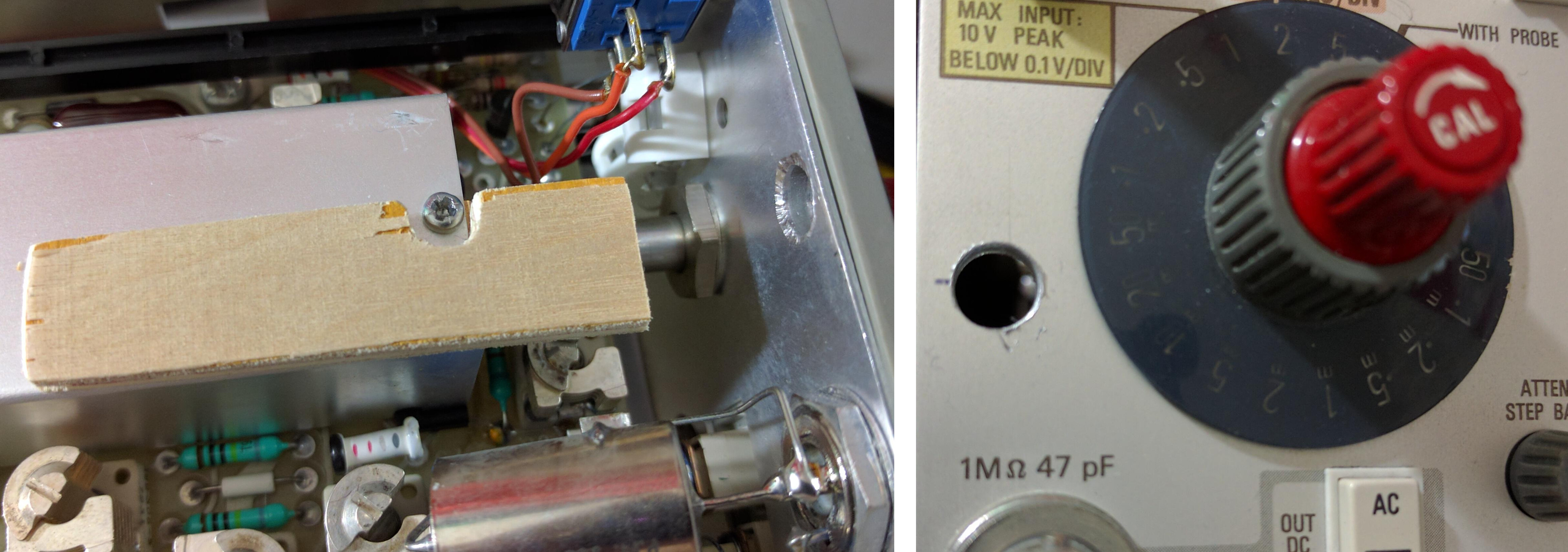
In the wiring shown below, the black wire connects to ground and the resistor lead (covered in red heat shrink tubing) connects to the wire going out to the x10 sense ring. When the switch is clicked out the two legs are internally disconnected and when it is clicked in the legs are internally connected.

And now I have a nice easy way to switch the scope between x1 and x10 mode.
Since I have a 3D printer I can’t help but model up some switch covers in Fusion 360 and give the whole project just a little extra finesse.
I’m quite pleased with the final result and it will make using the scope rather more convenient.