
Joule Thief
July 25, 2016
The Joule Thief is a fantastic intro to analog electronic circuits. The idea of a self-oscillating voltage booster is very old, but the current internet popularity (and name) is due to Clive Mitchel. I taught an intro to circuits workshop at my local makerspace using a slightly modified version of his circuit which used a capacitor to smooth the output voltage. The makes a great project for people to take home at the end of a workshop and covers soldering, resistors, diodes, LEDs, inductors, induced current, back emf, capacitors, and persistence of vision.
Below is my prototype for the class, the only differences are that I added a battery holder and used a slightly different switch.
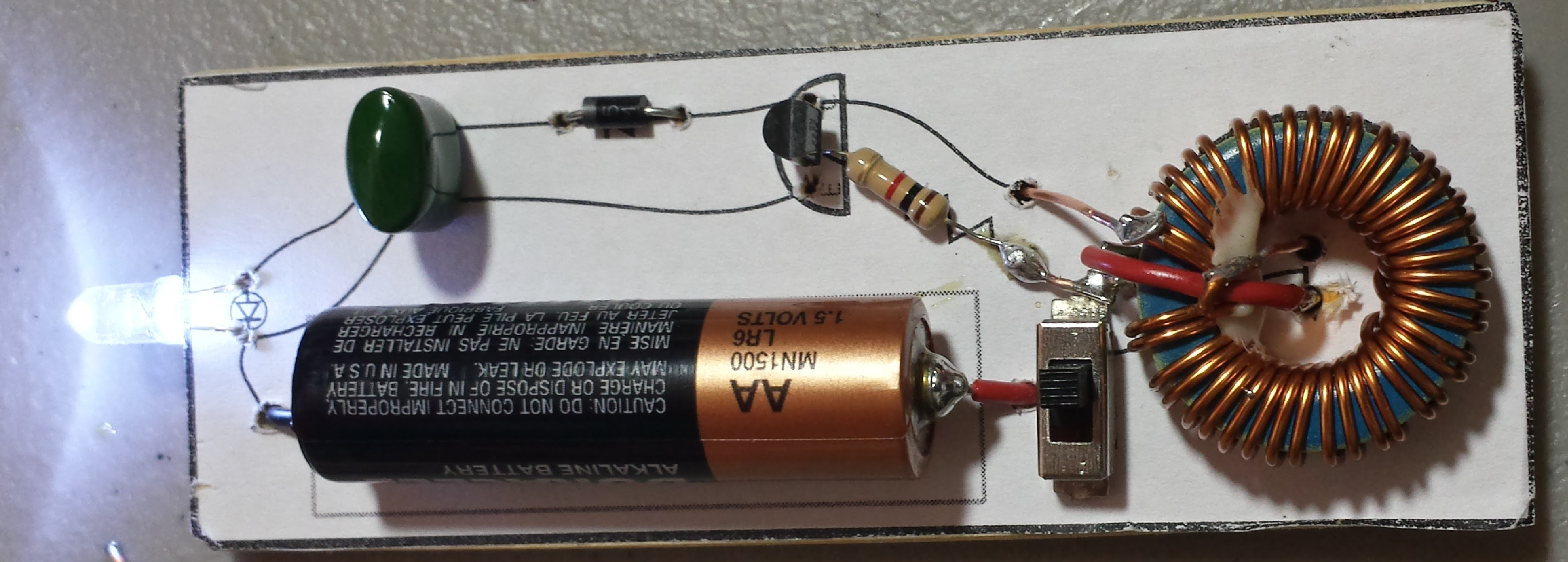
I wanted to be able to introduce all the basic circuit components and the standard circuit doesn’t have any capacitors. Adding in a small capacitor (and diode to force it to discharge through the LED) had the added benefit of keeping the LED on constantly instead of flashing at a few tens of kilohertz with an approximately 50% duty cycle. While the increase in brightness wasn’t huge, it was certainly noticeable.
Note: The two inductors in the schematic are a single double wound toroid. I suggest doubling up and pulling through two wires at once. Normal wire works fine, but magnet wire is nice since the insulation is so thin. The easiest mistake is to solder together the two wires at either the beginning or end of the coil. What should happen is that one wire from the beginning of the coil and the OTHER wire from the end of the coil should be connected together and then to the positive battery terminal. Those are the two I have going through the board in the center of the toroid and then connecting to the switch, which then connects to the positive terminal.

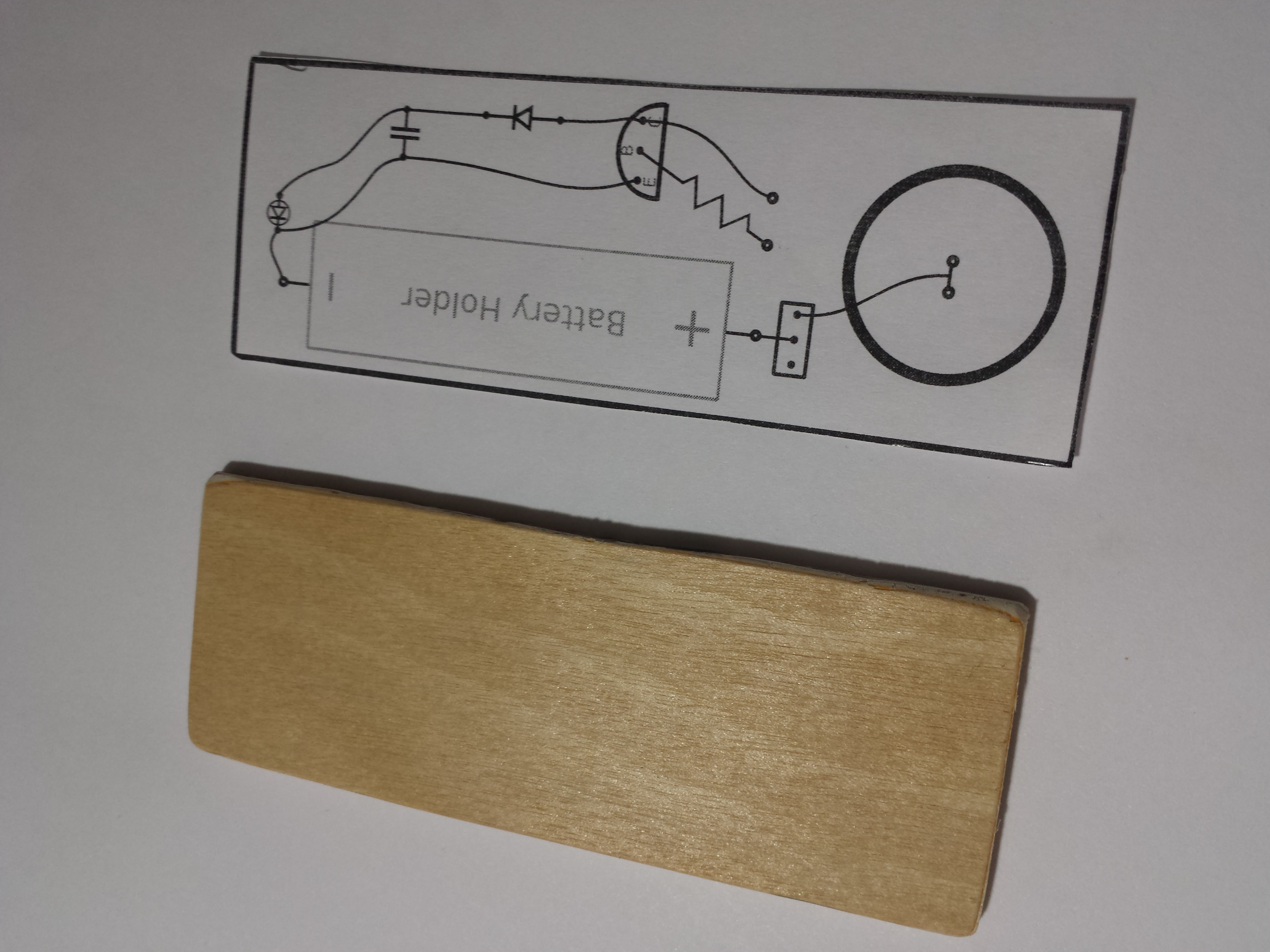
I also wanted the circuit to build into a useful form factor. Both so that members could practice soldering and so they would have more than a breadboard circuit to take home at the end. I thought about getting a PCB made, but I wanted it to feel less like a kit and more like a DIY project.
I sketched up an outline in Inkscape and cut some thin plywood to the proper size. Before the class I drilled all the holes in the wood and printed out a few pages of the outline. In class, once each person had their circuit tested on a breadboard, they glued the outline to the wood and placed all the parts.
Download PDF to print outlines Download SVG to edit outlines
If wires are left long enough, most of the connections can be made without and extra jumper wire.
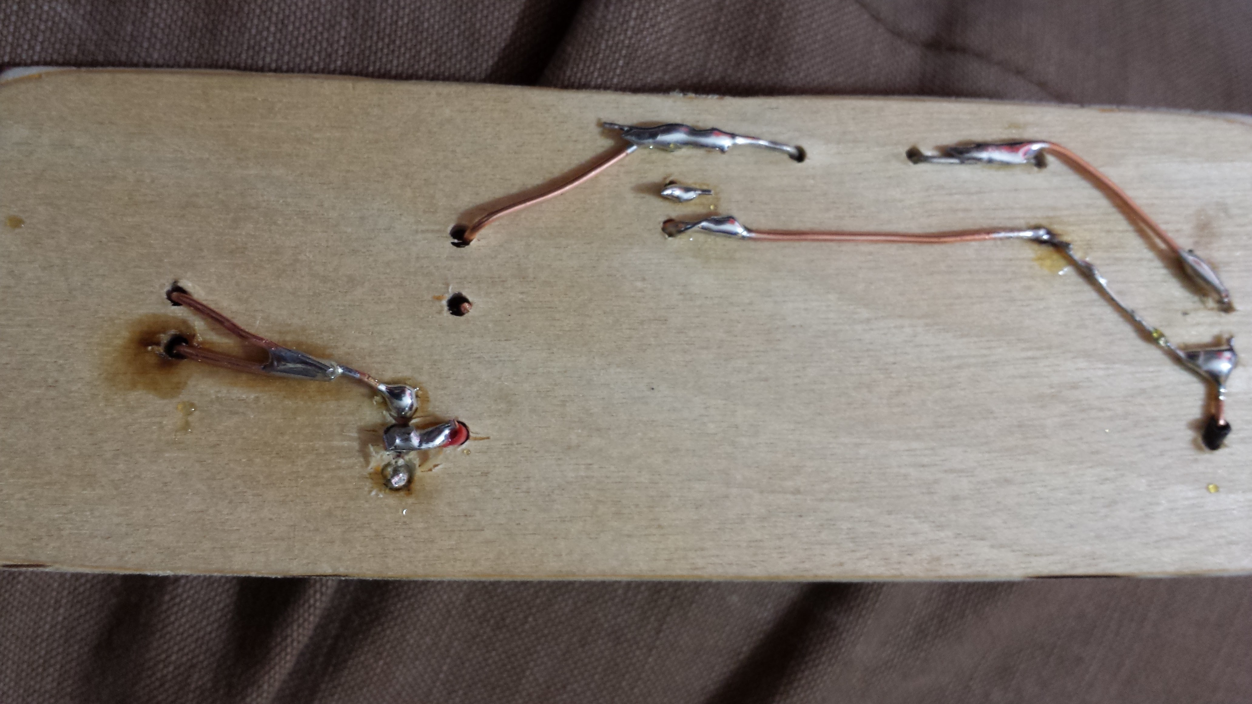
The circuit will run for a few days off of a “dead” AA battery and a few weeks off a new one.