Electronic Load
May 19, 2017
The simplest load is a plain old resistor, and for many testing applications that will be perfectly adequate. However, when testing power supplies and batteries one often needs to set the exact current draw and have it remain constant across a range of voltages. This video by Dave Jones showcases a simple design which uses an opamp in a negative feedback configuration controlling the base of a MOSFET to maintain the voltage across a sense resistor.
The Math
Mostly I want a load that can handle 1 or 2 amps for long periods, but I’d like it to be able to go up to 5 amps for shorter periods. A 1 ohm sense resistor must then be rated for at least 25 Watts (\( P=I^2R \)). I’d also like to be able to handle up to 30 volts at 5 amps which means the MOSFET must be able to dissipate \((5A)(30V)-25W = 125W\). The figure below shows the power dissipated assuming an ideal sense resistor and MOSFET as a function of current for various supply voltages. Fortunately I had on hand a few high power MOSFETs from an old receiver which meet the criteria quite nicely.

The IRFP450A MOSFET has a max drain-source voltage of 500 volts, a max power dissipation of 190 Watts, can handle up to 8.7 Amps at a case temperture of 100 degrees Celsius, and has a nice low drain-source on resistance of 0.4 Ohms. From figure 1 in the datasheet we can see that to obtain 5 Amps the minimum required gate-source voltage is 6 volts (and drain-source is 1.5 volts). Since at 5 amps the voltage drop across the sense resistor will be 5 volts, the opamp has to be able to output at least 11 volts and supply under test must be above 6.5 volts. Testing the opamp I’m using revealed that it can output up to Vcc-1.5V. Thus a Vcc of 12.5 volts is required.
The Parts
- LM358P Dual Opamp
- Potentiometer
- IRFP450A Power MOSFET (Datasheet)
- 1 Ohm 25 Watt Power Resistor
- Large heatsink with fan
- Thermal Paste
- 2 standard resistors for voltage divider
- Screw terminal
- 9 volt battery and holder
- Boost Converter
- Banana jacks
- Toggle switch
- Panel Voltmeter
- Copper clad board
- Feric Chloride
- Label backing paper
- Laser Printer
The Circuit
The circuit shown below is designed to connect directly to a 9V battery, but after I built it I added in a voltage boost converter in series with the battery to let me jump the voltage up to 12.5V. The voltage divider formed by R1 and R2 drop 9V down to 5V and the sense resistor of 1 Ohm gives a direct conversion to current. These can be changed such that the max output voltage from the first opamp is dropped down to a voltage equal in number to the max current you want the load to ever “ask for.”
A convenient result of using a 1 Ohm sense resistor is that I can use a simple panel voltmeter to measure the current to an accuracy decent enough for most of my applications. (Avoid the 2 wire meters which measure and power themselves from the same rail.) You might notice there are no dedicated connections for the meter on the circuit. I realized this too late in the process and so I just tacked the wires down at the appropriate points on the board.

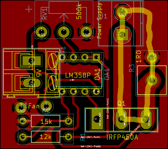
PCB Design
The image below shows a PCB design for this circuit created in KiCad. The main current loop is shown by the yellow highlighter. Parts can be directly soldered to the board but items such as the sense resistor, MOSFET, pot, and the terminals for connecting power supplies under test I connected via jumper wires so they could be mounted elsewhere. The low power traces and other tolerances are wider than one would usually make them since I wanted to experiment with etching my own board.
The two thick traces on the right side should be covered in solder to increase their current carrying capacity.
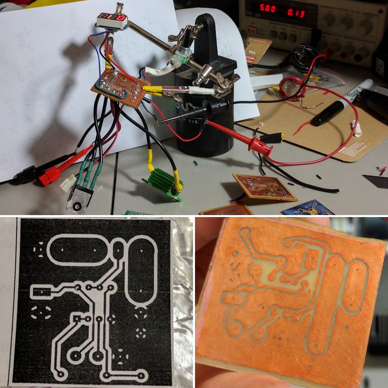
PCB Etching
After a variety of failures and running to the store for tiny carbide drill bits I managed to create a workable board with only one bodge wire (this has been corrected in the schematic above).
My etching process
- Export just the copper layer from KiCad (not mirrored)
- Cut copper clad board to match size
- Peel labels off of backing material and cut out a piece of backing material large enough to print the circuit on
- Rub the shiny side down with Acetone
- Tape to a sheet of printer paper using masking tape (print to paper first to be sure the location is correct)
- Print with laser printer
- Place toner side down onto copper clad board, cover with tin foil, and press down with a clothes iron for several minutes
- Carefully remove paper (may help to soak in a bowl of water)
- Place copper clad board in a Ferric Chloride bath and agitate until all visible copper is removed
- Remove toner with acetone
- Drill holes (the huge pain-in-the-ass part no one ever mentions)
- Place components on copper free side so that the legs stick through to the copper side where soldering will happen
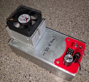
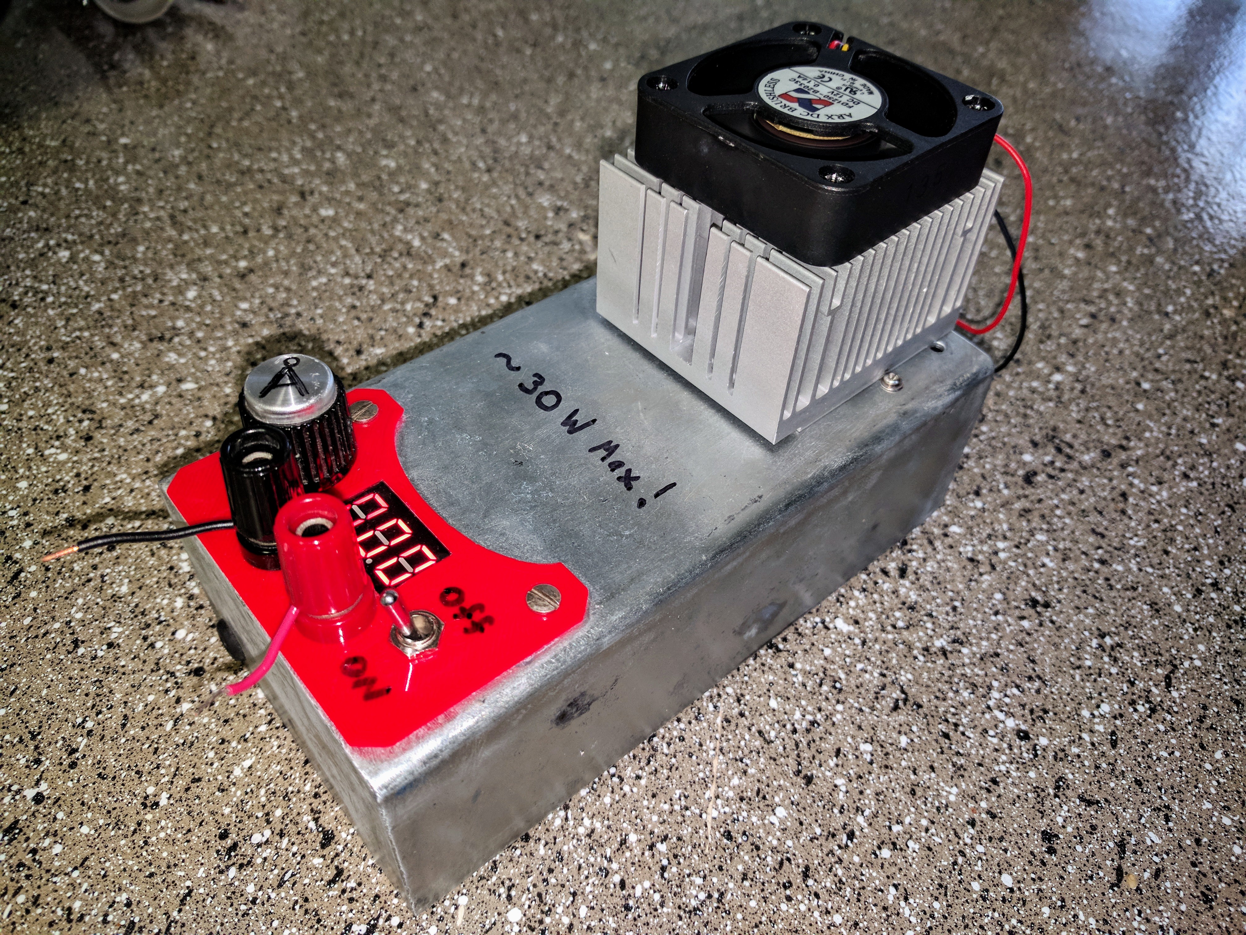
The Enclosure
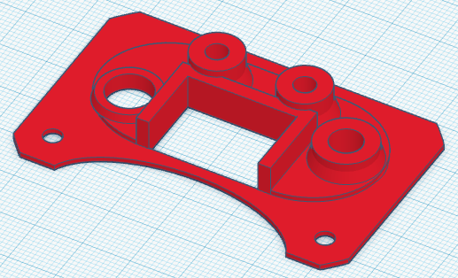
I used a steel box I had from taking apart some old broken equipment which I decided to use for the project box. The idea is that the whole container will form part of the heatsink. To avoid drilling into steel as much as possible, I designed an adapter plate to be 3D printed which would house the controls and fit into the odd oval-ish hole in the box.
Putting it together
I drilled holes in the housing and used M2 and M3 bolts to firmly attach the adapter plate, sense resistor, MOSFET and heatsink. Before mounting, thermal paste was applied as needed, and the MOSFET was electrically isolated using a mica sheet. I glued a section of foam to the case for the circuit board to sit on top of to prevent shorting the copper traces on the metal of the chassis.
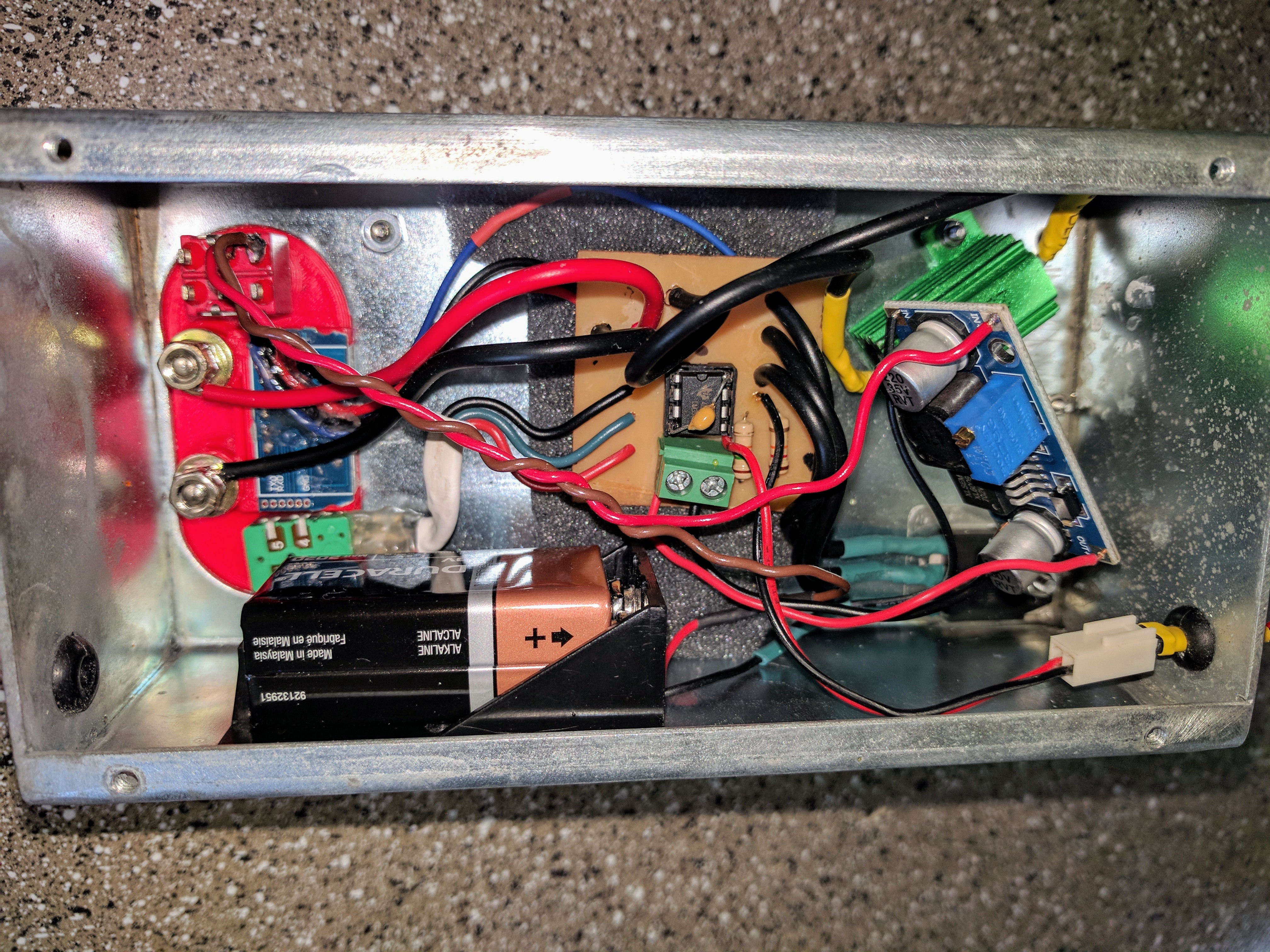
After some testing, I found that the max continuous dissipation in this configuration was about 30 watts and added that warning to the case.
Testing
The first plot shows what what the maximum current draw is as a function of the device under test voltage. In theory this would be that voltage divided by 1.4 Ohms (Sense resistor + MOSFET on resistance).

The second plot shows the maximum total power dissipated by the load at the same voltages.

Future Modifications
I went the battery route for extra portability, but it goes through batteries pretty fast when the fan is running so for long tests I’m going to add in a power jack.
I’m going to work on changing the heat dissipation setup so I can get at least 50 watts.