Characterizing a DC motor
November 20, 2018
In the process of going through the Robotics course on robogrok.com I realized I wasn’t sure what PWM frequency I should choose for controlling a DC motor. After some googling left my state of uncertainty unchanged, clearly the only road forward was to record much data and make many graphs.
These are the motor and motor driver I’m using.
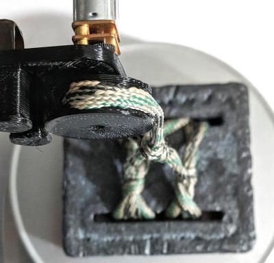
The setup shown below is for measuring torque. I’m using a PSoC 5LP dev board to control the motor driver. The power for the motor is provided by a linear bench PSU.
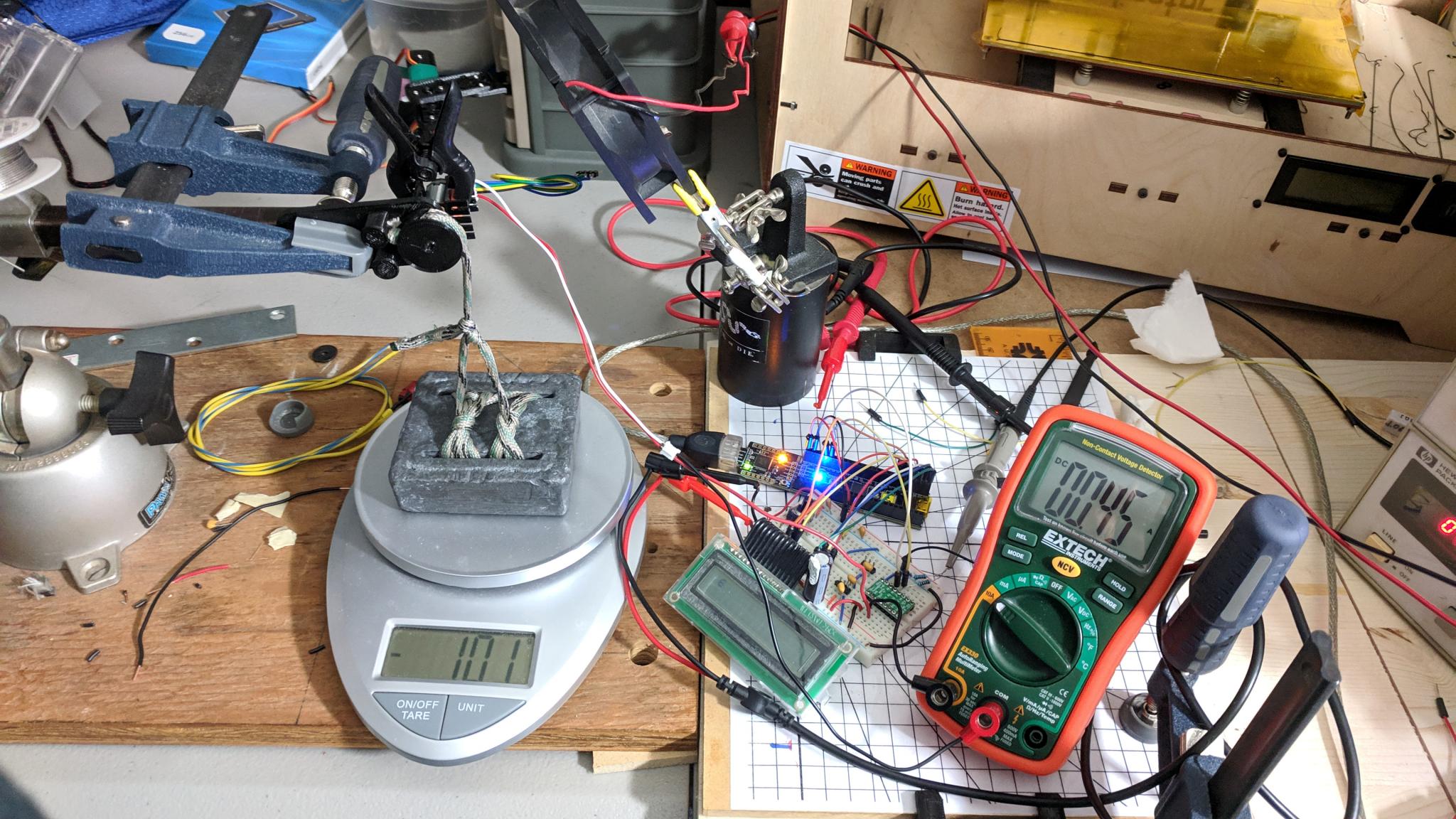
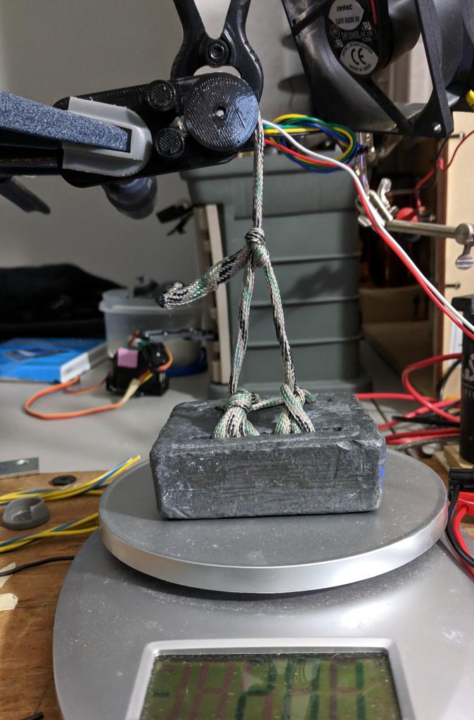
The motor is attached to a pulley which pulls up on a 3 lb lead weight. The scale is zeroed with the string slack so that the force exerted by the string pulling up is shown as a negative value on the scale.
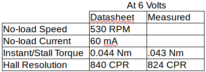
The first tests I performed were measurements of the no-load speed. The setup simply used the motor with the pulley attached but nothing connected to the pulley. This motor has a quadrature encoder and I used the 5LP to count the pulse edges coming from the encoder over a span of a 10 seconds 5 times in a row, averaged the values, and divided by 10 to get the counts per second. The number of counts per revolution I calculated by manually rotating the motor 20 times and dividing the resulting number by 20. (The LCD came in handy for displaying these values.) The counts per revolution came out to 824. (Note: CPR vs PPR) The RPM value is then (average counts in 1 second)/(counts per revolution)*(60 seconds per minute). Of course this is the speed at which the pulley is rotating, the motor speed is 30 times faster due to the gear ratio.
I ran tests at PWM duty cycles which correspond to 2, 3, 4 and 5 volts equivalent. Respectively 1⁄3 (33%), 1⁄2 (50%), 2⁄3 (66%) and 5⁄6 (83%) of the 6 volts provided by the power supply. (Frequency and duty cycle were confirmed using an oscilloscope.)
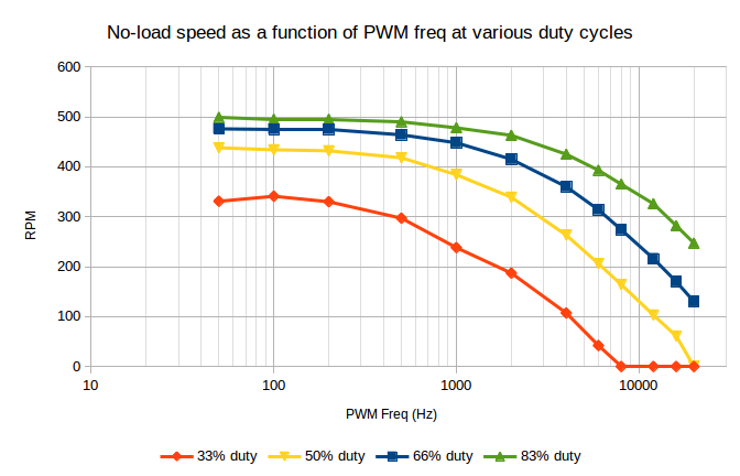
You can see that the speed stays mostly constant until around 500 Hz. By 1 kHz, and definitely 2 kHz, the speed has dropped off significantly, especially at the lower duty cycles. (Note the logarithmic x-axis.)
The plot below shows vertical slices through the prior plot. The speed isn’t quite linearly related to the duty cycle.

From the above results it seems like choosing a PWM frequency under 1 kHz is going to be a good choice.
The plot below shows the “lift mass” (reading on the scale) vs PWM frequency for various duty cycles. Since 100% duty cycle is just a constant 6 volts, this torque should be independent of PWM frequency and it does in fact stay within a fairly stable range, providing a sanity check.
Torque in Nm can be calculated using the equation below (where 0.011 is the length of the moment arm in meters and the lift mass is in kg).
\( \tau = (\mathrm{lift~mass})*9.8*0.011 \)
The measurement process:
- Rotate pulley fully clockwise (pause a few seconds to give the motor time to cool between tests)
- Rotate pulley fully counter-clockwise at some combo of freq and duty cycle
- Wait 10 seconds and record value shown on scale
- Repeat 5 times for each duty cycle
- Average measurements and calculate standard deviation
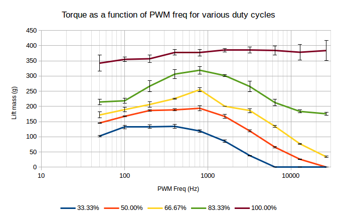
Interestingly this plot shows a peak in torque for three of the datasets at 800 Hz and at 400 Hz for the lowest duty cycle. This combined with the previous plots indicates that 800 Hz would be a good choice of PWM frequency.
The next plot compares the torque for a PWM signal driving the motor at 800 Hz to using a constant voltage. A PWM duty cycle of 33.3% with a 6 V square wave should be equivalent to 6*(2⁄3) = 2 volts. The other equivalent voltages are calculated in the same way.
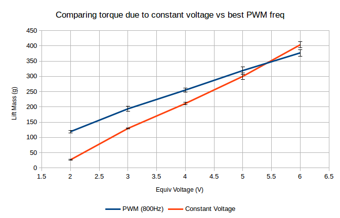
Interestingly the PWM signal consistently beats out the constant equivalent voltage, though what should really be compared is the current. (The 6 volt data points should be identical since the PWM signal is at 100% duty cycle, I suspect the difference between them may be due to temperature differences in the motor windings).
Speaking of the windings, let’s examine them a bit closer. Measuring the inductance with my LC meter gave a value of about 2.15 mH (at a measurement frequency of about 71 kHz).
Measuring the winding resistance with both my LC meter and with a multimeter yielded resistances of about 10 Ohms. For a more accurate measurement I measured the current through the stalled motor for a range of voltages, shown in the plot below.
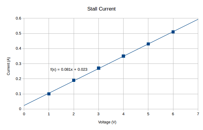
Resistance is the inverse of the slope which yields a value of about 12.4 Ohms (for a fairly cold coil).